Fun with the Arduino UNO and a NES gamepad

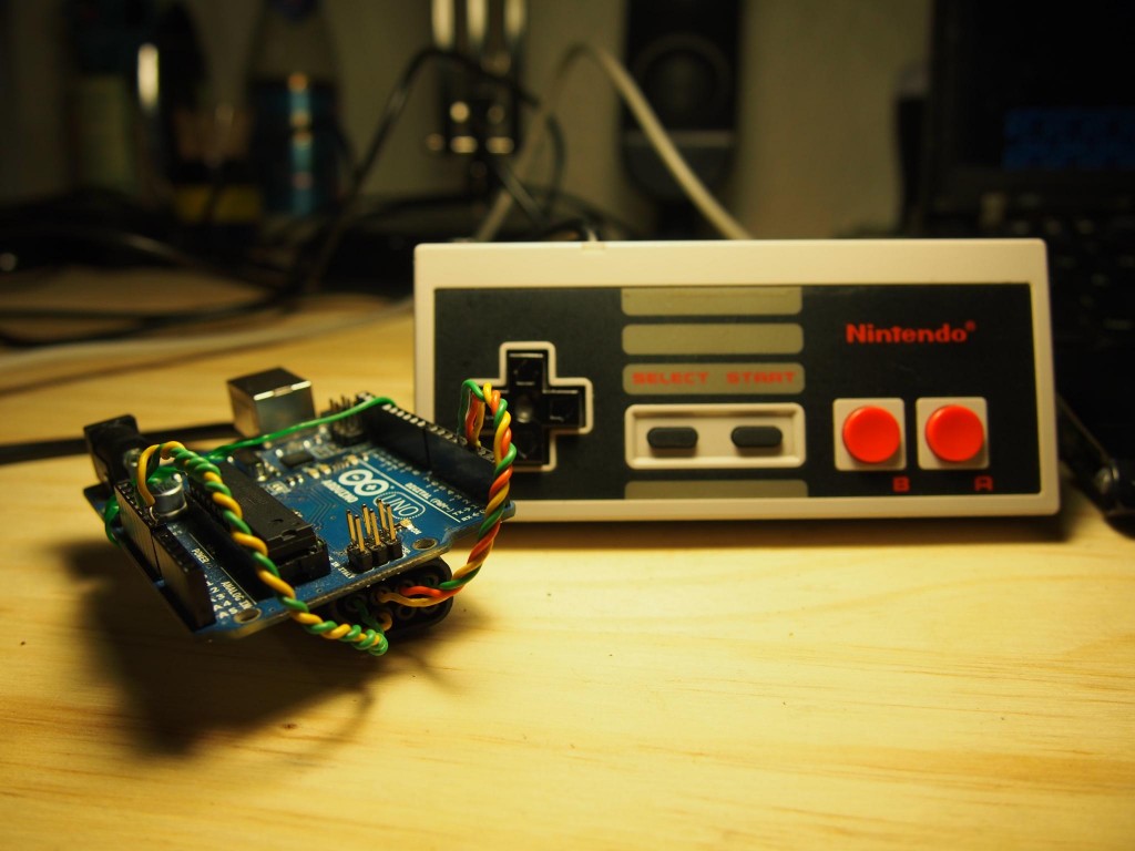
A while ago I wanted to play the original NES. It turned out my console was broken and so, decided to find a way to connect the NES gamepad to the computer using an Arduino.
I looked on the Internet and found many things, but not exactly what I wanted:
What I found
- Read the NES gamepad from an Arduino
- Emulate a keyboard on the computer, and interpret Arduino serial input as keyboard presses.
- How to build USB firmwares for AVR microcontrollers. How to build an USB firmware for AVR that acts as a gamepad.
What I wanted
- A NES gamepad that showed on the computer as an USB game HID: something you can plug into any computer / console and will (hopefully) work out of the box, plug and play.
So, all the pieces for the puzzle were there, and the only thing left was to put them together. Now that it’s working as I intended to I have decided to write this post to save some time to anyone interested in building similar things. This post might be too verbose for the purpose of this thing, but what’s the fun on putting something together you can barely understand? I decided to spend more time than usual inspecting all the things involved on the process.
Note that these are not the instructions on how to do it, but a mix up of story, missing gaps of information I found, or at least some useful information to lower the entrance barrier a bit, and some reference links. For instructions check the repository.
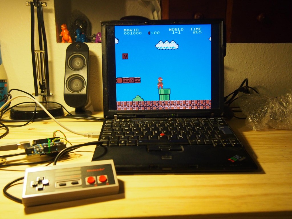
TL;DR: I put together a USB HID gamepad with the NES controller and an Arduino. Also, first post.

Onto the NES Gamepad
The NES gamepad has a 8-bit shift register that, upon receiving a LATCH saves the state of the 8 buttons (GND means pressed). Clocking a signal through the CLK line, the state byte is shifted through the DATA pin.
    NES gamepad controller pinout

        o 4    1. +5VDC Supply                            INPUT
    1 o o 5    2. ?
    2 o o 6    3. ?                                 _|_|_|_|_|_|_|_|_
    3 o o 7    4. GND                   LATCH  ____|                 |
               5. CLK                              |     IC 4021     |
               6. LATCH                   CLK  ____|\                |----- DATA
               7. DATA                             |/                |
                                                   |_________________|
           ________
    LATCH |        |
    ______|        |______________________________________________________________________________

                     ____      ____      ____      ____      ____      ____      ____      ____
    CLK             |    |    |    |    |    |    |    |    |    |    |    |    |    |    |    |
    ________________|    |____|    |____|    |____|    |____|    |____|    |____|    |____|    |__

         _  ________  ________  ________  ________  ________  ________  ________  ________  ______
    DATA  \/    A   \/    B   \/ Select \/  Start \/   Up   \/  Down  \/  Left  \/  Right \/
         _/\________/\________/\________/\________/\________/\________/\________/\________/\______
                     |--12µs--|
A diagram on extracting the input from a NES gamepad. Some pins on the IC 4021 omitted for clarity.
The following code outputs the input from a NES gamepad in binary words.
int CLK = 2;
int LATCH = 3;
int DATA = 4;

byte last_read = 0xFF;

void setup();
void loop();

void setup()
{
    Serial.begin(115200);
    pinMode(CLK, OUTPUT);
    pinMode(LATCH, OUTPUT);
    pinMode(DATA, INPUT);
}

void loop()
{
    byte reading = read_NESpad();
    if (reading != last_read){
         Serial.println(reading, BIN);
    }
    last_read = reading;
}

byte read_NESpad() {
      /*
        NES Word Mapping
        x x x x x x x x
        | | | | | | | |_  A
        | | | | | | |___  B
        | | | | | |_____  SELECT
        | | | | |_______  START
        | | | |_________  UP
        | | |___________  DOWN
        | |_____________  LEFT
        |_______________  RIGHT
     */

  // Send a HIGH pulse to latch. Make 8 shift register store state
  // of all buttons
  digitalWrite(LATCH, HIGH);
  delayMicroseconds(12);
  digitalWrite(LATCH, LOW);

  // Clock the 8 shift register to get the
  // state of the buttons
  byte output = 0x00;
  for (int i = 0; i < 8; i++){
      output |= digitalRead(DATA) << i;
      digitalWrite(CLK, HIGH);
      delayMicroseconds(6);
      digitalWrite(CLK, LOW);
      delayMicroseconds(6);
  }
  return output;
}
This was enough to build a minimum viable hack, consisting on an arduino sketch reading the gamepad and sending it through the serial interface and a Node.js (\o/) server reading it and firing xdotool to emulate key presses. Ugly, but enough for a hit of nostalgia for the rest of the weekend (if you really want to see, it lives on this branch). With this I was on the same as most of the links I found googling around.
After playing with it for a while I sort of felt this was well behind my initial goal. Which I initially wanted was to actually build an USB gamepad you could plug onto your friends’ computers, no install, no anything. Upon researching, I found out that meant flashing a new firmware to the UNO, even if I did not really understand what that meant.
A little guide on Arduino and DFU
Instead of using an specific purpose USB-to-serial chip, the Arduino comes with an ATmega programmed to act as an USB to serial device (so you can upload compiled bytecode from sketches into the EEPROM). That’s what gets detected when you connect the Arduino into the computer. In better words:
The Uno differs from all preceding boards in that it does not use the FTDI USB-to-serial driver chip. Instead, it features the Atmega16U2 (Atmega8U2 up to version R2) programmed as a USB-to-serial converter.
http://arduino.cc/en/Main/arduinoBoardUno
    ____________________
   | o       ···········
RESET ---> + · ·
GND -----> + · ·
  _|____
 |      |
 | USB  |
 |______|
   |
   |
In order for the Arduino UNO to appear (and act) as a different device, a new firmware has to be flashed into the ATmega16U2, by putting it into DFU (direct firmware upgrade) mode which, depending on the board, is done with more or less messy ways which for older versions may require soldering.
Hopefully my board is an R3, which can be cleanly put into DFU mode by jumping the RESET and GND pins on the Atmega16U2 together for a fraction, using a jumper or, if feeling wild, just a piece of copper.
Looking for inspiration
At this point, I did not really know what to do. I could read the NES gamepad from the Arduino using sketches, and was able to flash new firmwares onto the arduino, next step?
LUFA
LUFA (Lightweight USB Framework for AVRs, formerly known as MyUSB) is an open-source complete USB stack for the USB-enabled Atmel AVR8 and (some of the) AVR32 microcontroller series, released under the permissive MIT License (see documentation or project source for full license details). The complete line of Atmel USB AVRs and USB AVR boards are supported by the library, as are any custom user boards, via custom board hardware drivers supplied by the user.
http://www.fourwalledcubicle.com/LUFA.php
Darran Hunt’s Arduino Hacking blog has a nice set of posts with examples on how to build different HID devices using LUFA and Arduino. In particular, there’s one example that emulates an USB joystick with two axis and two buttons, which is almost what I needed. The example is, at the same time, based on one example from the LUFA library, and Arduino’s USB-to-Serial firmware.
HID Devices interact with the USB stack using HID reports. The firmware describes itself as an USB HID Joystick and reads on the serial interface from the main processor (the ATmega328), which means it can read data from the main code (sketch, running on the ATmega328) to the firmware code (running on the ATmega16U2). The sketch handles all the input, and sends it through the serial interface using a packed struct. The firmware just roams there, waiting for data, and then sends it to the USB stack as a proper HID report.
I found Darran’s design on this issue pretty clever and on the line of what Arduino is supposed to feel like. The firmware is doing all the heavy lifting, and all the logic lives on the sketch.
Note that there was no real need to compile a modified version of the firmware. I could be ok by using one example that has 40 buttons, and throttles and more axis. But when I get into something, I really want to understand how all the parts work together. If not, it’s almost time wasted.
HID report descriptors 101
For the USB stack to know what device is it talking to, and how this reports do look like, it uses a descriptor table. In this descriptor table you fill up everything about your device: what’s its purpose, what type of device is it, how many inputs it has and how are they represented. Oh, and it has to be 8 byte aligned, which means adding a padding every time you are sending less than a byte. Everything is documented on the USB HID Specification document (have fun with it).
Some reference links: [wikipedia] [USnooBie’s USB HID Report Descriptor Tutorial 1]

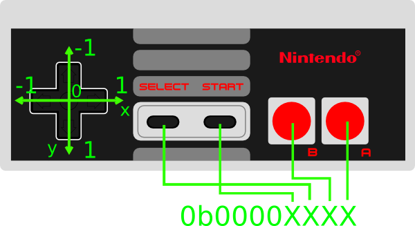
2 Axis
Min Max Value (-100, 100)
2^3 = 8 (size, signed integer), #2 (axis)
4 Buttons
size 1 (boolean), # 4
+ 4bits of padding.
Device and manufacturer ID
Devices identify themselves using a device and manufacturer ID. For acquiring one yourself you would have to pay large sums of money to the USB foundation. I have decided to leave the original Atmel Corp. LUFA Joystick Demo Application.
The whole thing
Hacking a firmware yourself
You’ll need to:
- Set up the LUFA environment
- Read these posts in Darran’s blog, just for reference.
- Take an example from the LUFA library that suits what you want.
- Look into arduino’s usb-serial original firmware.
- Combine them both to interface with the Arduino.
- Write your HID Descriptor
- Start hacking.
Chicken and egg
At this point, I assume I could be doing all the ‘nintendo’ parsing part on the firmware, be it by directly interfacing with the INPUT ports or just getting the 8 bits through the serial interface instead of the whole HID Report, but that would make it too specific. Having just a firmware that does one thing, and does it well just keeps everything simpler.
But being that Arduino is meant for easy hacking into microcontrollers, that would not make much sense, and I would be better by just glueing an atmel microcontroller into a NES Gamepad.
Conclusions
After this I would love to put together a project to ease the creation of USB game devices, just by using the arduino library, similar to unojoy. While describing a 30 button – 6 axis – 1 hat switch device could be enough to have a generic firmware, I want my devices to appear on the computer exactly as they are. What I think of would be some compilation variables or a descriptor generator, and then a different protocol of communication between the sketch and the firmware.
Also, I cannot wait to get more gamepads of consoles I did not have, like the SNES and the N64.
Finally, it will be interesting to put two gamepads together on the same board and make them appear as two devices by using report ids on the HID descriptor.

Thank you for writing such a detailed post about your experiments. I’m researching the idea of something very similar to this, except the arduino would accept several different types of controllers and connect to the computer via Bluetooth. Nice work!
Koks geras straipsnis!
awesome
55 thousand Greek 30 thousand Armenian